
How To: Bluetooth Headphones for
Hearing Aids
(Winter 2008)
This project was conceived in my head for a fair number of months before I carried it out. But I should probably explain what it is and "why," and I'll try to be concise.

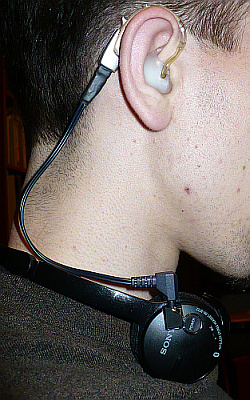
What you see in the above picture is a set of bluetooth headphones around my neck. There's an audio jack spliced into the "phone", and a wire goes from this jack to my right hearing aid. There is an identical setup on the other side. The headphones can sync with my bluetooth MP3 player, my laptop, or a bluetooth cellphone. I can then listen to audio, or have a phone conversation (the headphones have a built in microphone, and it works great) wirelessly. Sure, this has wires, but they don't get in the way, usually.
My alternative is to use regular DAI cables. Plenty of disadvantages with those however. They're wires, so I'm tethered to either the laptop or my mp3 player. MP3 player can go in my pocket, but the wire has to be untangled initially, and then gets tangled in clothing and is very prone to opening the battery door on my hearing aids (that turns them off, of course). If tethered to my laptop, I can't go anywhere without unplugging something. Using the headphones, I can move around freely... roughly 30 feet from the source, or up to two walls in between. The headphones have volume and song selection controls on them as well, so buttons are always accessible.
There's lag in the connection... so it's not ideal for videos on the computer. When both my BT mouse and these headphones are synced to my computer, I sometimes get laggy behaviour from one or both after a while. The BT mouse likes to randomly disconnect itself too, regardless... resetting that involves toggling the bluetooth hardware in the laptop, and the headphones have to be re-paired too.
Battery life is great: up to 11 hours says the manual... I've not really counted (because 11 hours straight is a long time), but I've gotten at least 9 hours on a charge.... The MP3 player only does 5 hours.
Being concise is not my strong point, but there's lots of details I find interesting in this.
Below is a work in progress – a guide on how to do it yourself. Unlikely though it may be that you could use this.
Supplies
What you need:- A set of Bluetooth headphones (Might well want to use the ones I used)
- Two audio jacks
- Soldering iron and solder
- One DAI y-cable (this will be chopped up)
- DAI boots/shoes for the hearing aids
- Two 270k Ohm resistors or 330k Ohm... actual resistance subject to trial and error and personal opinion
- A few inches of 1/4" Heat shrink tubing
- Two sets of headphones from which to take the audio plug and ~8" of wires (two strands is easier to work with; one strand probably works better when being worn)
- Dremel (or other effective cutting tool)
- Various other tools or ingenuinity to replace
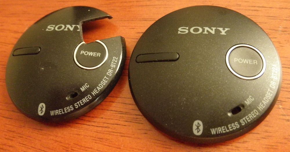
- Sony DR-BT22 Bluetooth headphones
- Two mono audio jacks from Digi-Key
- Three old monaural DAI y-cables from Phonak (Because I ruined some via trial and error)
- Two 270k Ohm resistors (red purple yellow [gold/silver])
- Three sets of Jensen Lightweight Stereo Headphones (because I lost the first wire I made) 1 2
- ...
Modifying the
DR-BT22 Headphones
First step is to familiarize yourself with the contents and how to open
up the headphones. For future reference, phone refers to one
side's ear piece.... They're called headphones and that's what there
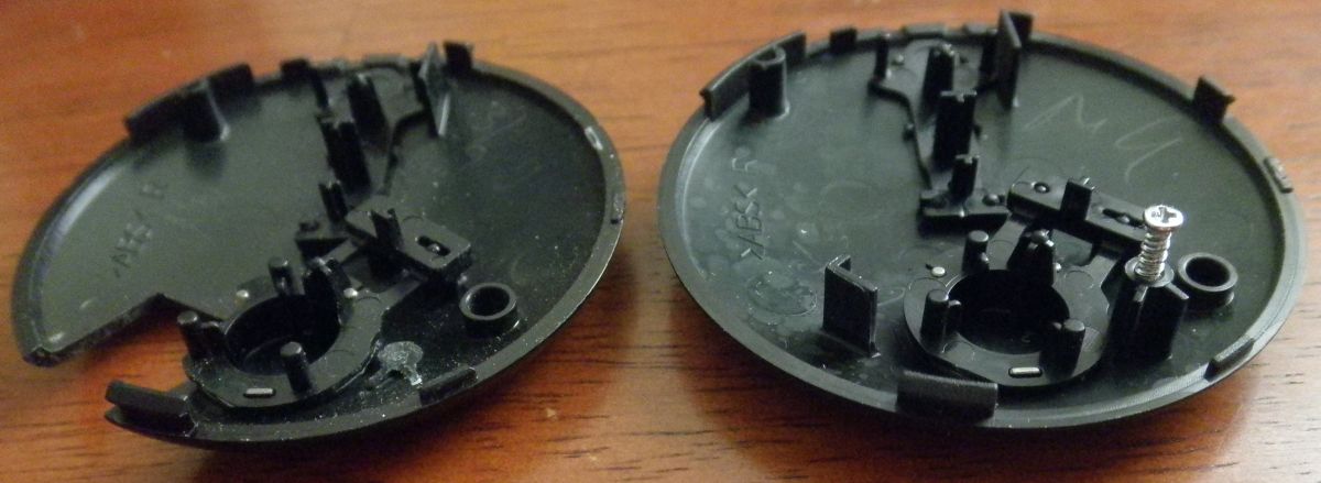
are two of, so makes sense to me...First, you need to pry out the side with the speaker of each phone. It's a bit tricky I broke at least one of the claw-tabs. This hasn't been a problem, but still, be cautious. As picture indicates, there is a spot to insert a flathead screwdriver. Pry it open slightly. Then use the flathead in one of the other openings to rotate the speaker piece so that it pops all the way out.

You then remove the single screw in each phone that will be visible. I've never reinserted said screws... The hole for the screw on the right phone was useful for running wires to where they needed to be.

On the right speaker, you can go ahead and desolder both wires... BUT first make sure to mark which went where. (I don't actually know what all of those contacts are for...) Alternately, you can just wait until later to desolder those. You might want to just use the right phone for testing purposes initially, i.e. verify everything else still works.
The left phone's speaker can be reinserted. Those two wire connections will remain intact. Prying off the outer cover of the left phone exposes the battery, a small PCB (printed circuit board), and a fair bit of open space.


The battery can be pryed off its adhesive, and then unplugged. Alternatively, you can remove the PCB to make unplugging the battery easier (User manual recommended method). DO NOT trim the battery's casing at any point unless you want to risk necessiating a $43 replacement battery.... Happened to me.

Next, you need to decide where you're going to place the audio jacks, so you know how long your wires need to be. As for the jacks themselves, besides form factor, they're all pretty similar in style. Just make sure you have the ability to solder wires to their terminals.
I found two possible jacks pretty quickly, and went with the cheaper, and larger of the two. Both are designed for surface mount applications (i.e. circuit boards, but this is not important) and are monaural/mono (cheaper/better for this purpose). Slim version and wide version. Both can be purchased through Digi-Key. You could use stereo jacks too, but that just costs more... unless you salvage your jacks from old cassette players/mp3 players.
You can either jump right into soldering, or do a bit of testing first. I did testing by first desoldering (see following paragraphs) a couple of wires and then making all the electrical connections with alligator clips and plunger clips.
Having found where you plan to put the jack, and the necessary wire lengths, cut wires and start soldering.
On the left phone, two wires connect the small crescent shaped PCB and the speaker. Desolder the red wire from its spot on the PCB, and solder it to terminal 3 of the jack (see image). Solder a second wire to the same spot on the pcb as the black wire. Solder its other end to terminal 1 of the jack. Solder a third wire to where the red wire was attached to the PCB. Solder it's other end to terminal 2.

Now that you have the left phone rewired, test the headphones. With nothing plugged into the jack, the speaker should work normally. Plugging regular stereo earbuds/headphones into the jack will produce sound in the left bud/phone. If it doesn't work... check the wiring again, perhaps check for continuity, and check the right phone if you didn't disable it earlier.
Now you need to mount the jack. I used a chopped up LEGO piece as a spacer, and epoxied the jack onto the phone. I then used my dremel and patience to make a rectangular cutout for the jack in the outter cover of the phone. I didn't get a perfect fit, but such isn't necessary.
Give adequate time for the epoxy to harden. And you might well have to redo the epoxy later on... I've redone the epoxy on each phone twice, I believe, but the latest time has held up for over a year. This was probably due to the challenge of getting an equal mix of tiny amounts of epoxy to make the strongestbond, the first two times.
The right ear is trickier, because you have less room with which to work, and wires to manage. Ultimately, the jack is in the same approximate spot, but offset due to the power button. In trimming the cover, I cut a chunk of the power button out as well, and it works fine. There's also a plastic riser that one of the removed screws went into. Removing this bit gives room for the wires to come out, as seen below.
Creating the DAI
Wires
In case you hadn't noticed the mouseover text every time I use "DAI,"
(and if you were actually wondering) it stands for "Direct Audio Input."Below is the the basic electrical diagram of a stereo y-cord. It's very simple, but also important. The resistor in the circuit is found either at the point where the DAI cable splits into two cables, or within the audio plug iteself. This merely depends on the specific cable, and is not important here.
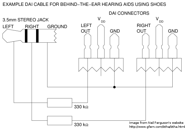
What is important is that the part of the y-cable containing the resistor is being thrown aside. You'll need to replace the resistor in each of the two short DAI cables of this setup. I did a bit of testing to find what resistor size I wanted to use. Neil recommends 330,000 ohm resistors. I found 270 kohm to be ideal for me. You should test for yourself.
All of the wires I've made for these headphones have been the combination of a y-cord, and the wires from a pair of cheap headphones, specifically these ones. The right angle plugs work much better than a straight plug would. And yes, it took 3 pairs of headphones two make one pair of awesome headphones.
More
info:
Here are some links that I found useful during the course of this
project.- Various sources of DAI y-cables:
- From Phonak through your audiologist: Monaural y-cable
- The Hearing Loss Help Co.: Stereo
y-cable (dead link; new link might be these) Currently using these.
- Connevans (UK): Stereo y-cable If you have these in the US, don't destroy them... I'll trade you phonak wires for them... Seriously.
- Know of others? I'd love to hear of them.
- Neil's guide
- The headphones I take the stereo jack/plug from: Amazon.com (Used to be cheaper)
-1-10-10