
Components:
- NIKKO Alienator R/C Toy Car (circa 1985)
Included:
- 7.2v motor (Mabuchi RS-540SH)
- (All other electrical components junked)
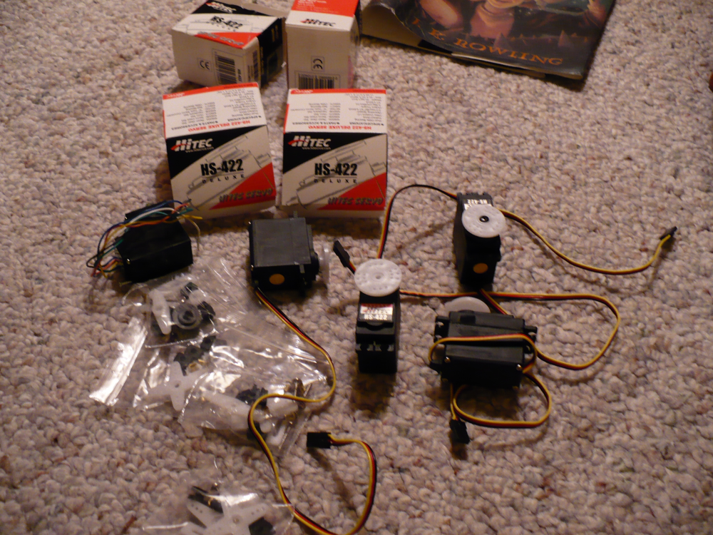
- Three Hitec HS-422 servos
- Mini SSC II servo controller
- Two 9V batteries (rechargeable NiMH)
- Four AA batteries (rechargeable NiMH)
- 3 watt 25 ohm potentiometer
- Heat sink (from old CPU... to be used on potentiometer)
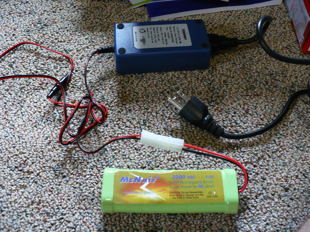
- 7.2V rechargeable toy battery (NiMH 3200mAh)
- 4-wire telephone cable
- Serial adapter hardware
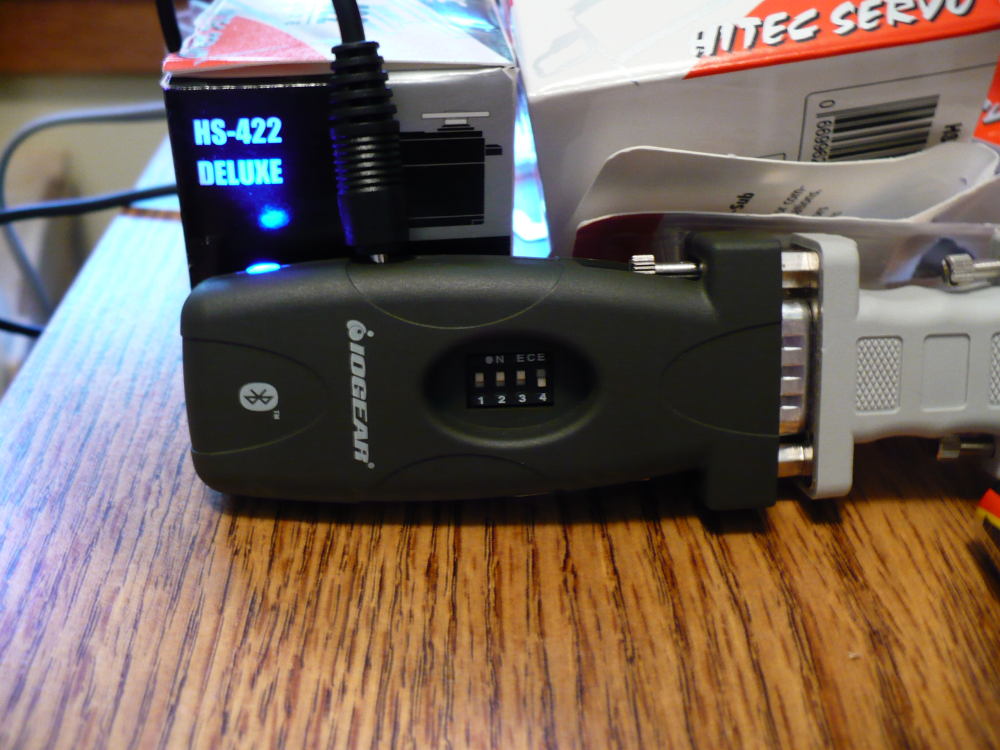
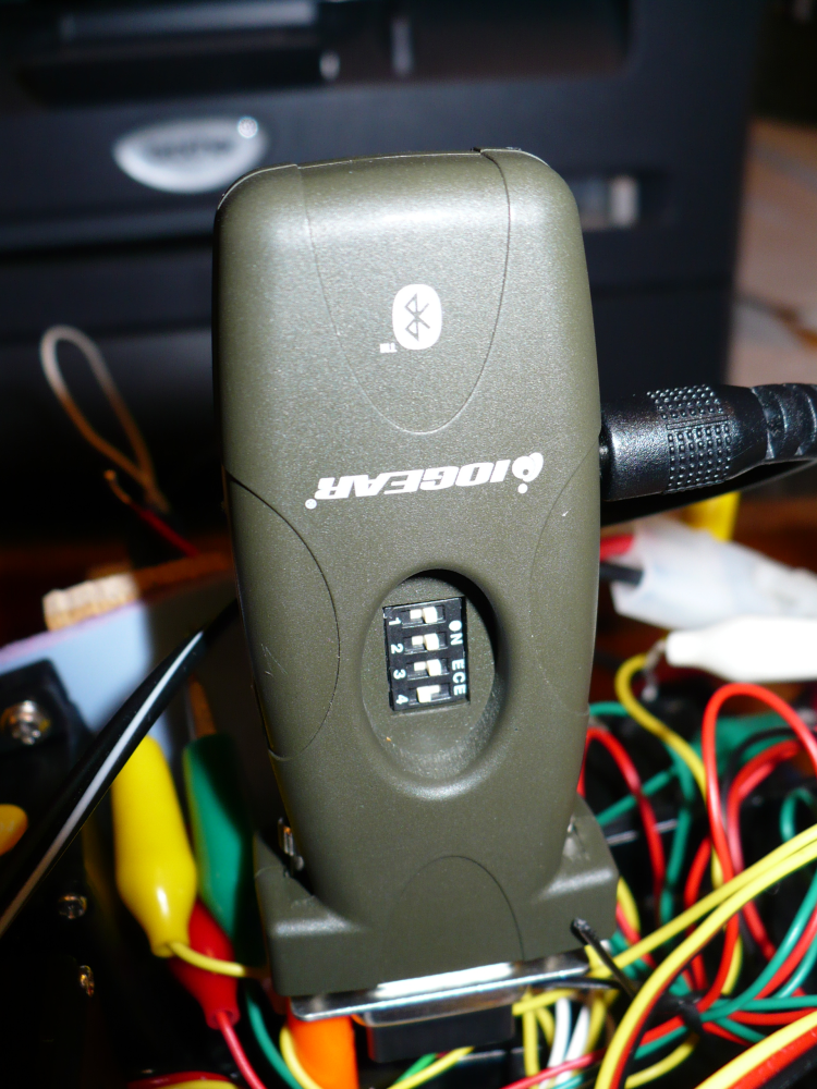
- Bluetooth RS-232 Serial Adapter (Iogear - GBS301)
- 8 alligator clips for temporary wiring (temporary because I use the servo controller for other projects, too)
- A computer with bluetooth class 1
(class 1 has the greatest range)
My first step in starting this project was reading about half
of everything I could find on the subject. I recommend it for
anything you do of this sort.... I approached this whole project
with a "know before you buy" mentality.
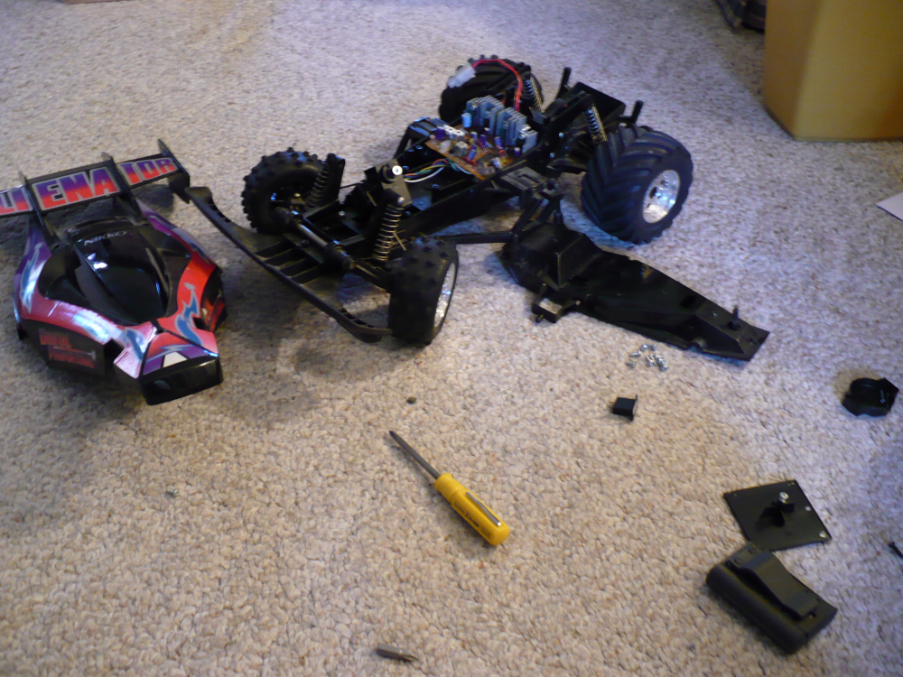
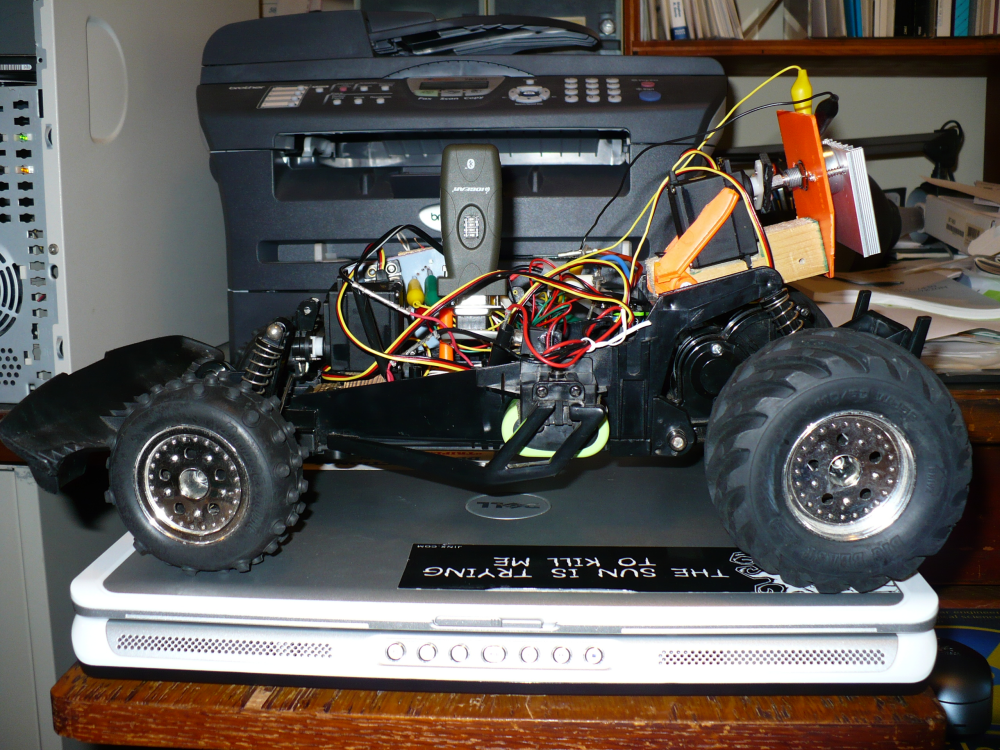
I then proceeded to find a suitable toy car... I couldn't think of any
friends of mine that had one I could use and I wasn't interested in
garage sale hopping, so off I went to eBay. The NIKKO
Alienator, sans remote controller was one of the first and in the end
best (dirt cheap) options I saw. It was also lacking a
battery (I'm sure the original, if this car is really two decades old
was shot anyways) and electrical connectors for the 4 AA battery holder
on the underside.
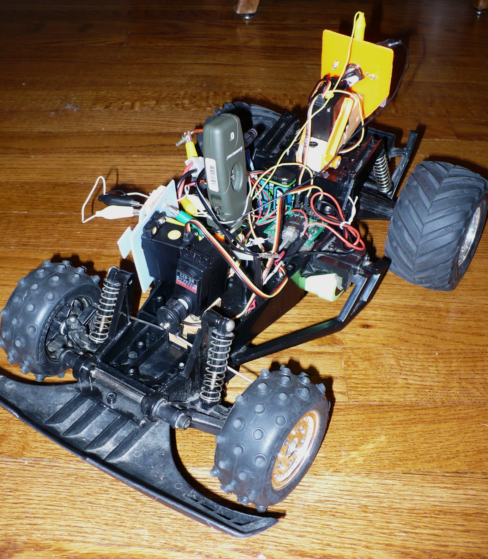
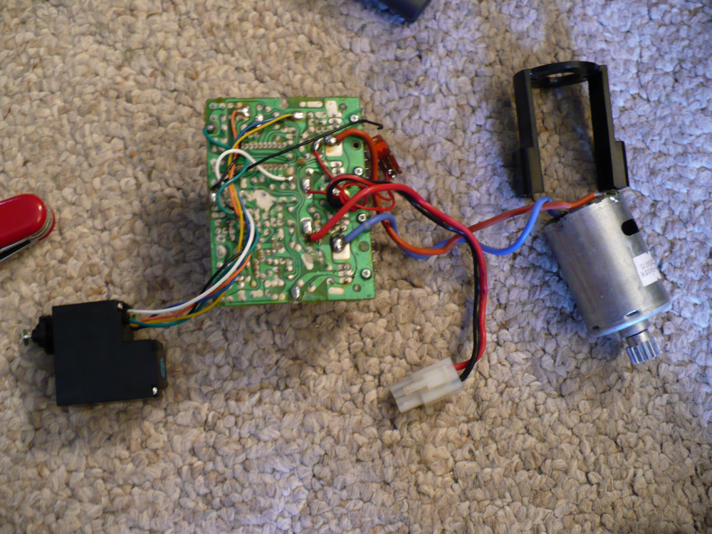
Upon returning from vacation to a large box with the car (larger car than I
expected, but in hindsight, a good thing) I of course took it apart,
and discerned that the only thing of real use on the car besides the
chassis was the motor.
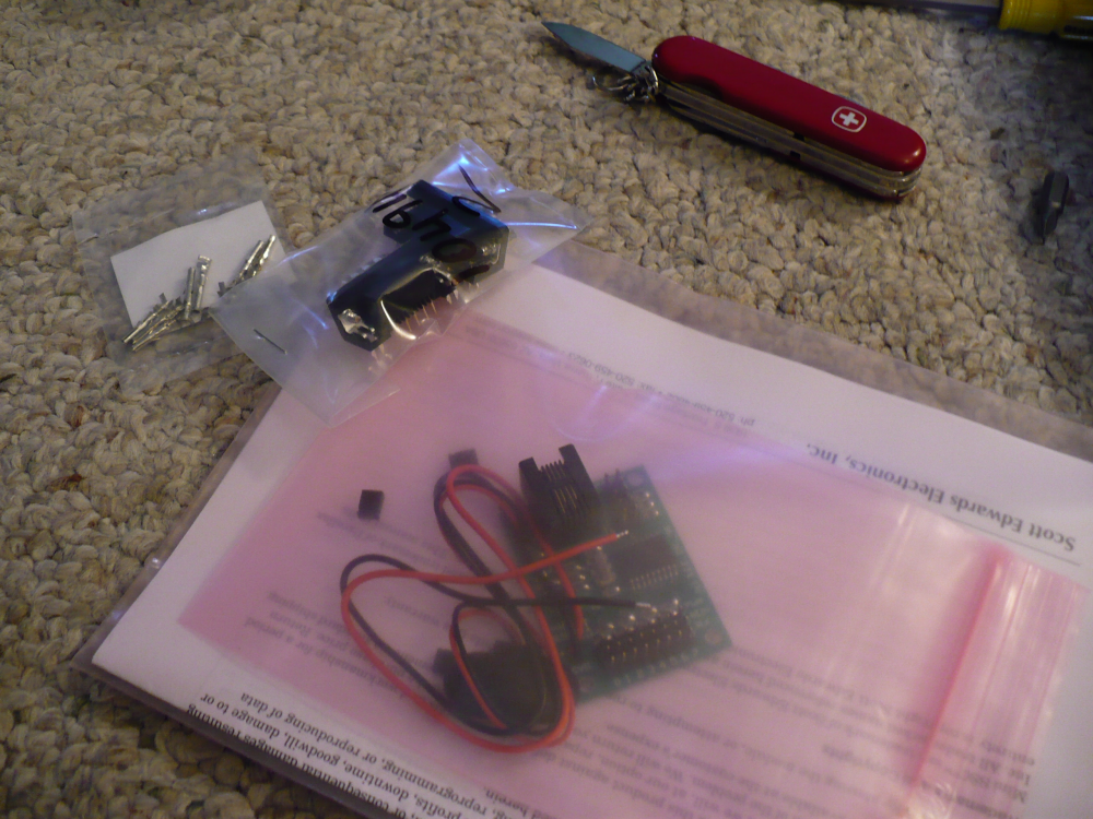
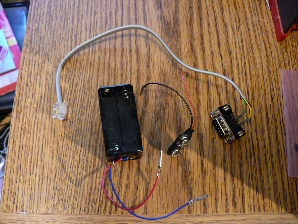
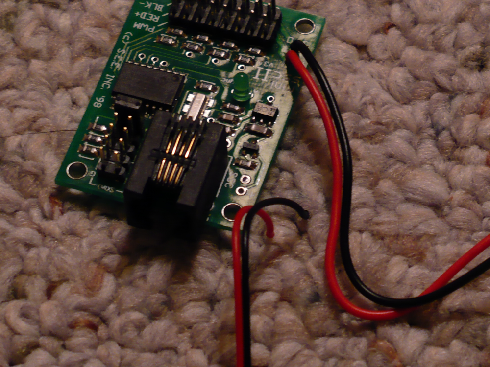
I started with salvaging the telephone wire and then wiring the serial
adapter for the Mini SSC (4).
The male 9 pin serial adapter was probably supposed to have
wires soldered to it, but I went with crimping (with pliers) connectors
on the end of wires. Didn't work too well.
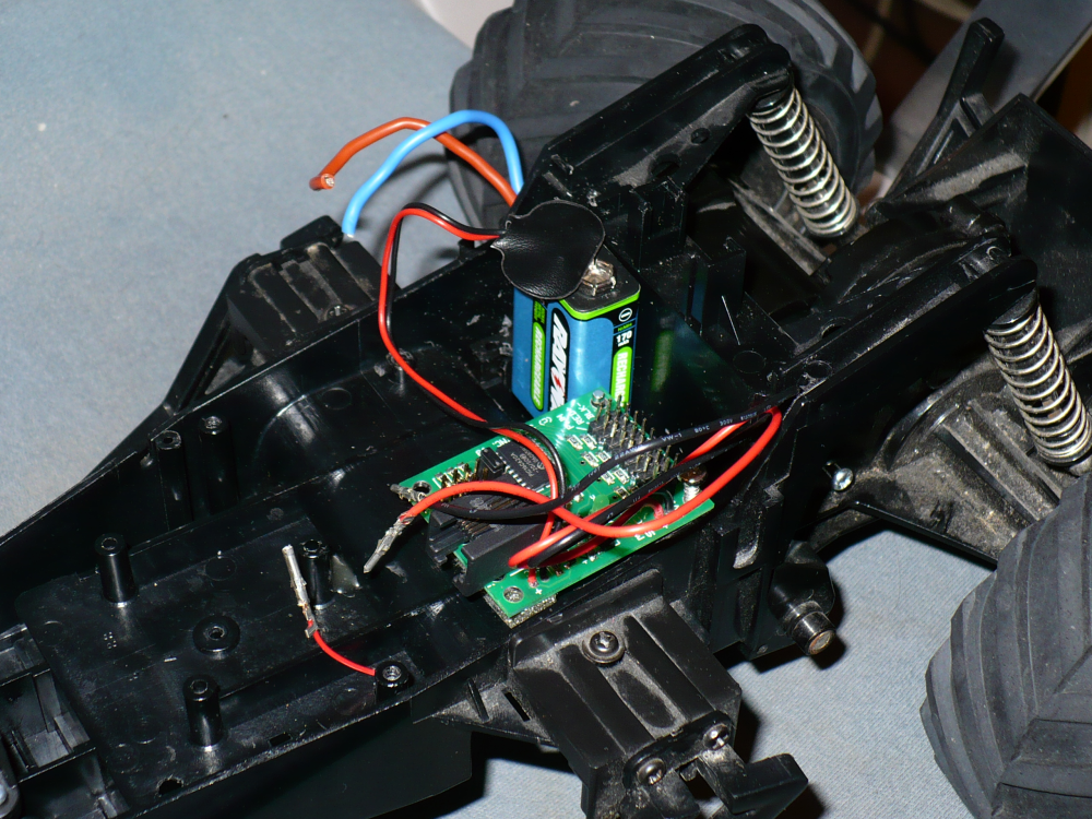
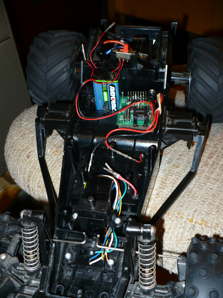
Mounting the Mini SSC and it's 9V battery was quite straightforward.
I simply did a bit of looking for where stuff would fit.
The 9V battery is snuggly held between some ridges of
plastic. It was just my luck that the mounting holes on the
Mini SSC with two holes that alread existed for screws right next to
the battery's spot. (5)
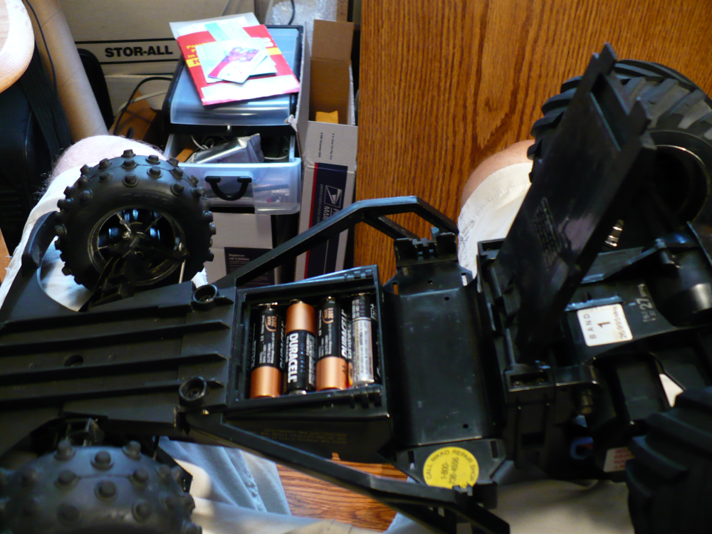
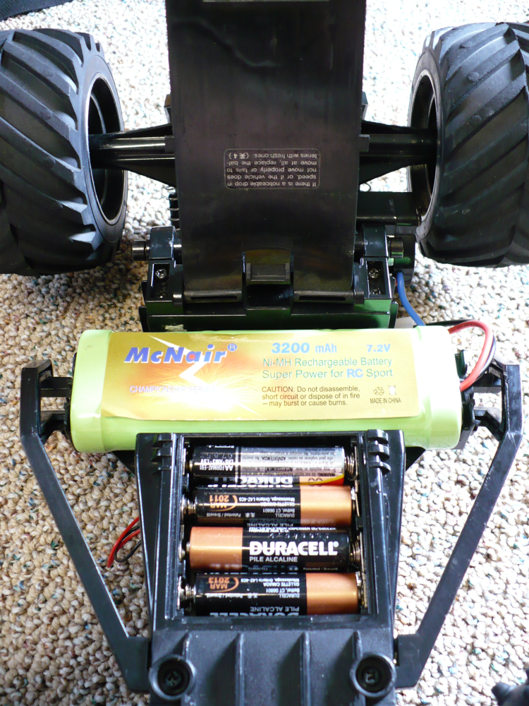
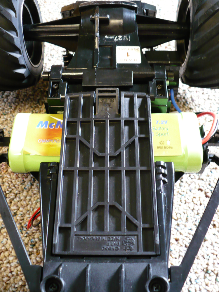
I didn't discover the compartment for four AA batteries on the car for
around a week. The underside of the car has a 'door' that
slides and pops into a locking position. Opening it gives you
access to where the 7.2V battery goes. It also covers up a
placeholder for the AA battery compartment. (9,
13) The compartment
didn't have any terminals with which the batteries would have been
electrically connected. I salvaged the necessary parts from
two Hot Wheels chargers and two old lazer tag guns.
I bought two 7.2V NiMH batteries plus a charger on
eBay at the same time I purchased four servos (spares are a great thing
to have). (11, 27)
Those two purchases were 40-50% of the project costs... and
obviously I can use them for future projects. So I view that money as a reasonable investment.
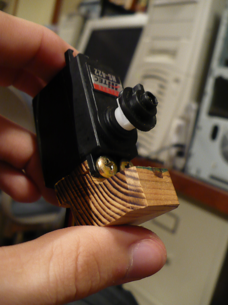
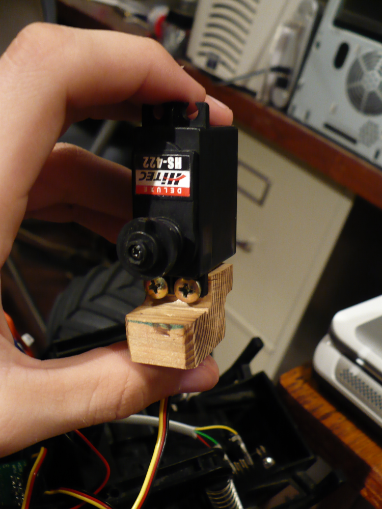
Once the servos arrived, I started with mounting the steering servo.
It didn't fit in the spot that contained the original, ancient, six
wire servo, so I had to mount it elsewhere. I chose to use a
wood block (19) to fit where the
old servo had been, and mount the new servo to this block. I
started with shaping a foam block to the shape then rough cutting the
wood, and fitting it using a grinding wheel. (I lacked the ideal
tools...) Once mounted, the wood started to crack due to
drilling smaller holes for screws than I ought to have. (19)
Once I better understood
the mounting hardware that the servos came with, I replaced part of the
wood block.
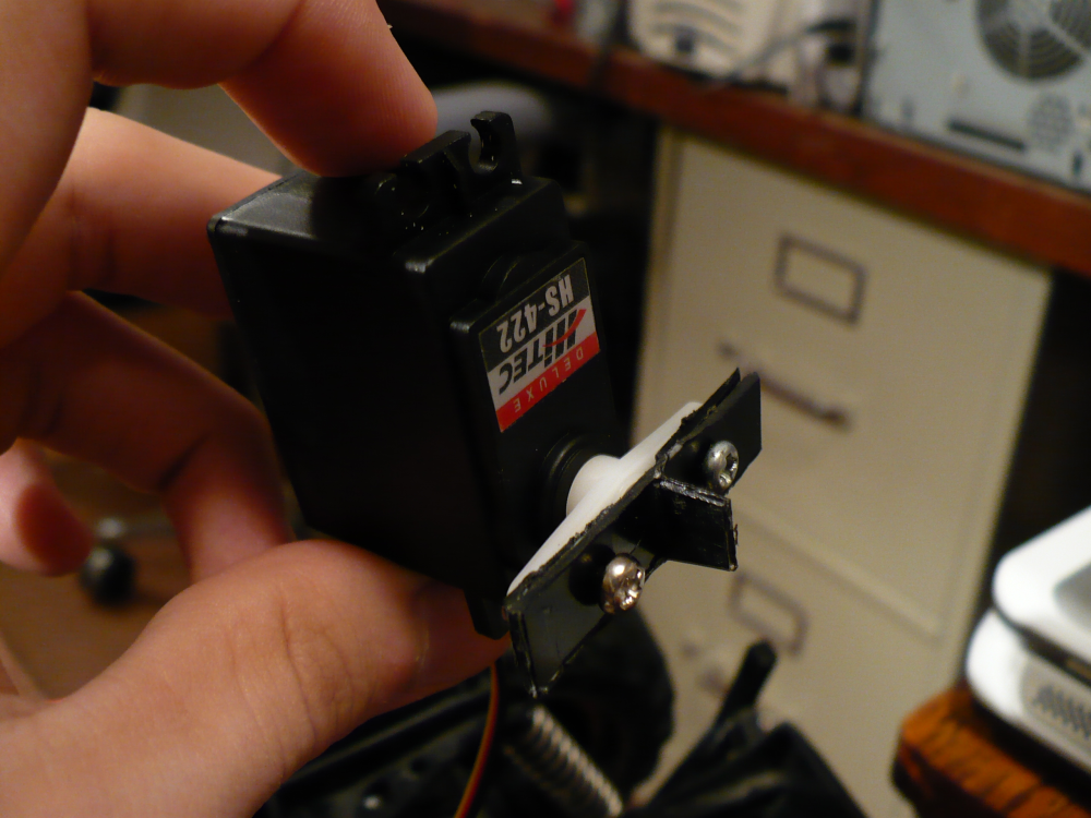
The linkage between the servo and the front wheel is mechanically a
weak point, though it's supposed to be. The concept of a
"servo saver" is that the mechanical linkage will fail between the
wheels and servo before damage is done to the servo. Ideally,
this linkage is easy to reset if broken. Alas, I wasn't fully
able to use the servo saver that the car came with, but my current
implementation works so far. The entire servo can actually be
dislodged rather than take damage, and this happened a lot when driving
over rough ground. I've since implemented a spring system
that pulls the servo back into its slot, removing the need for manually
reattaching the servo.
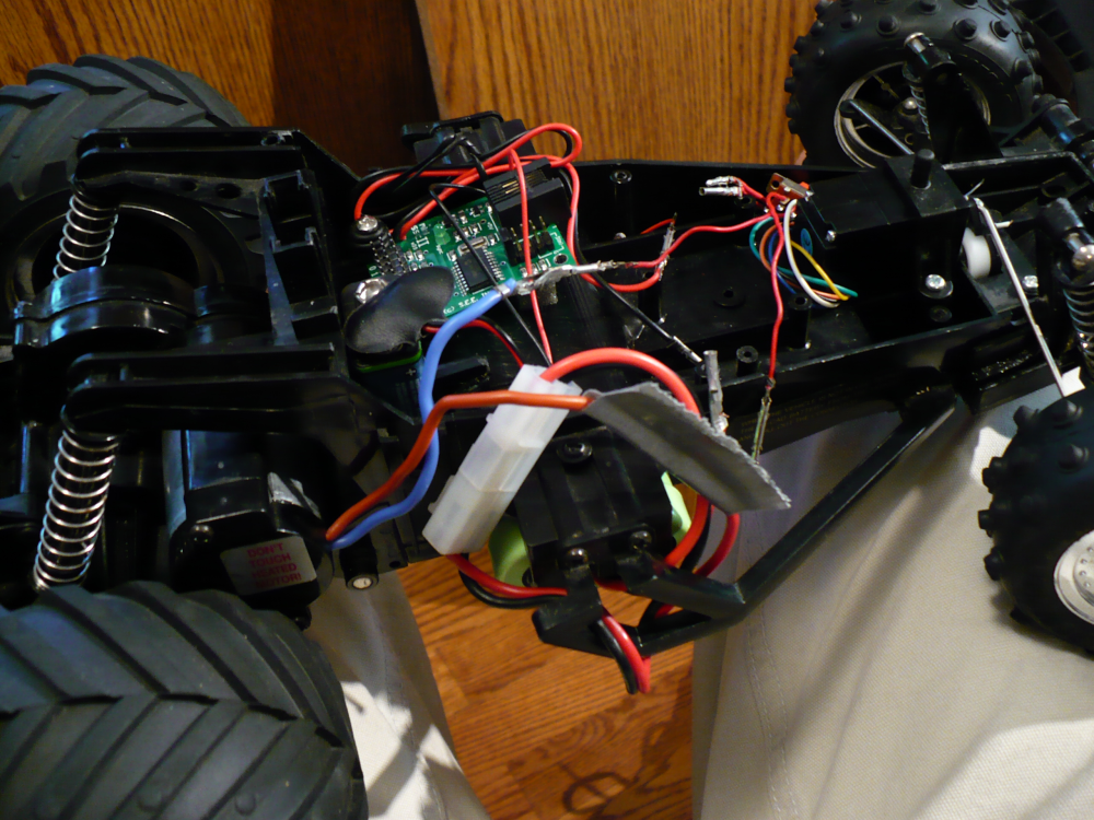
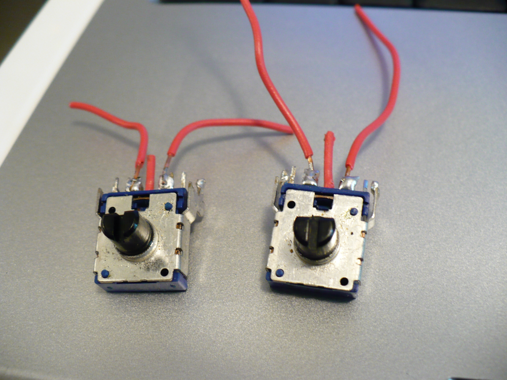
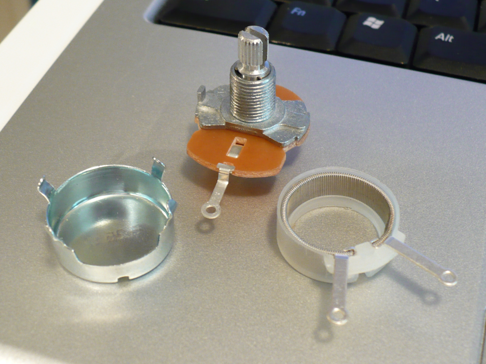
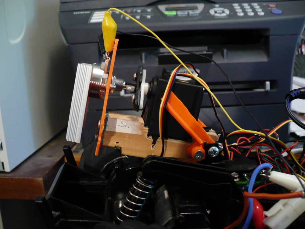
For speed control, I decided to use a potentiometer. By
varying the resistance, with constant voltage, one varies the current
that the motor can draw. Initially I salvaged a couple of
pots from a recently replaced radio. They worked for a few
seconds until some magic smoke
escaped. I followed up with a 3 watt, 25
ohm (that's the resistance range, not maximum resistance) potentiometer
(actually, a rheostat)
from RadioShack.
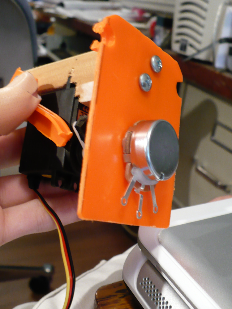
I had to be cautious with the new potentiometer too - it builds up a
fair bit of heat in the circuit I was going to implement it in.
I disregarded this fact in my initial testing and ended up
burning a small portion of the insides. (26)
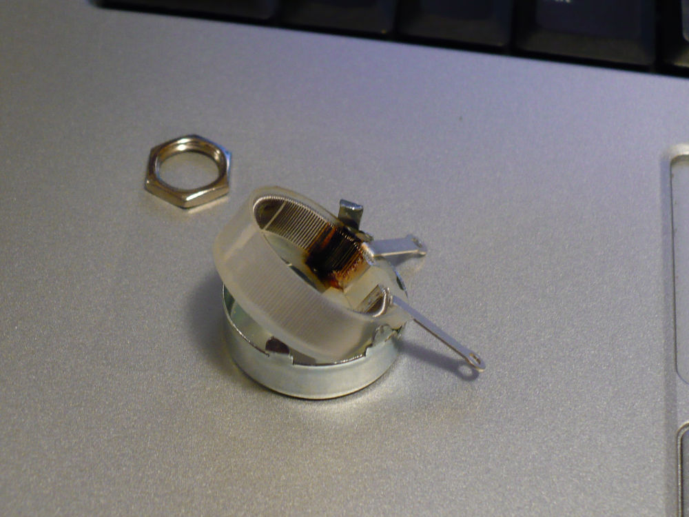
Thankfully, when using a potentiometer as a variable
resistor, you only need two of the three terminals
I decided to modify the potentiometer. They still build up
heat even if the motor isn't moving, and that's wasting energy.
My solution is to turn part of the potentiometer into an
on/off switch by destroying part of the resistive coil inside.
This creates a section where current can flow with varying
resistance, and then a section where, due to the break in the coil,
current can't flow.
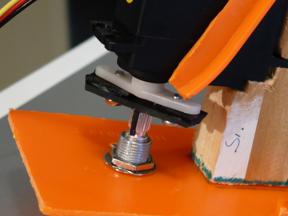
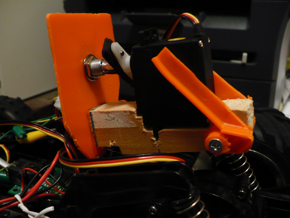
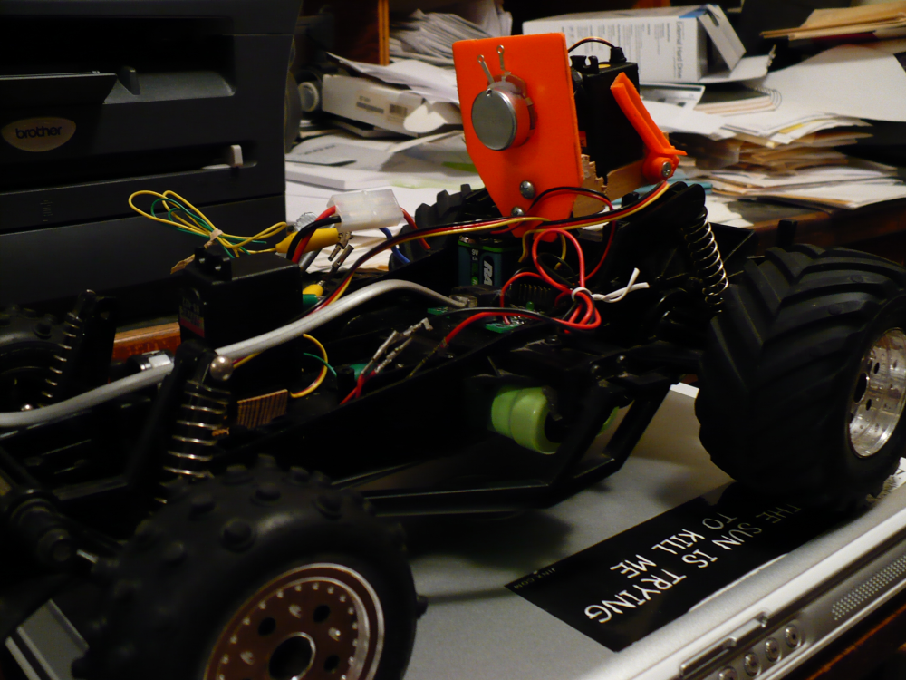
For the servo that would actuate this, I created a neat looking mount. (21) I cut the servo's profile
into a piece of wood, making sure I had a snug fit. I lined
up the servo's shaft with that of the potentiometer and then mounted
the wood piece to a piece of plastic that the potentiometer was already
mounted to. This assembly is attached to the car in a shaky
makeshift manner, but it has yet to break or show any signs of wear...
It just shakes a lot as I drive the car.
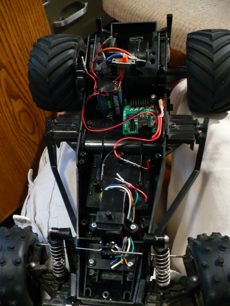
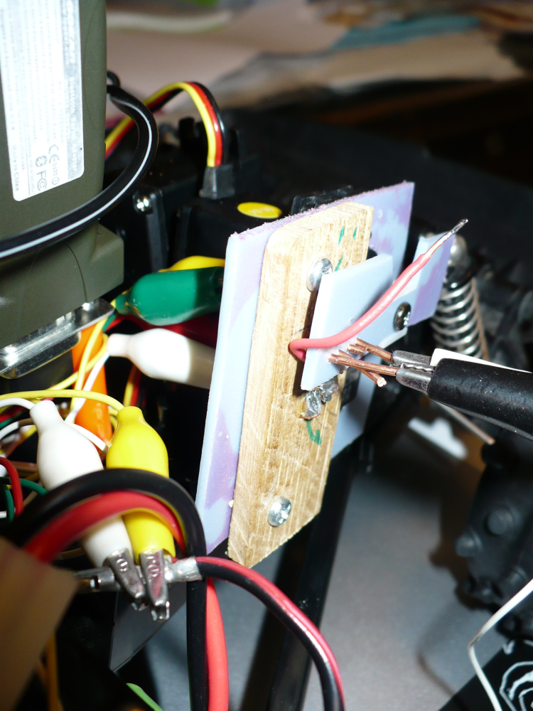
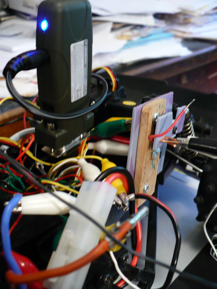
The third servo on the car is used to control the motor direction by
reversing polarity of the power circuit. This is accomplished with an
arm on the servo that moves to make the proper electrical contacts. (31) It's a rather touchy
implementation. With better tools, I could do something more
compact and less finicky. I've replaced the system entirely
once with only a slightly better end result. Oh well.
I'll probably post a simple circuit diagram in the future. If
I wanted to pay the cost of the Mini SSCII again, I could buy a
dedicated motor controller with built-in H-bridge.
Beyond that, everything else was a matter of making sure stuff was
nicely attached and wouldn't go flying.
To begin with, the actual function of the bluetooth in this project is to create a wireless version of a serial cable connecting a computer and the servo controller on the car. RS232 is the standard for the 9 pin serial connection. You can learn quite a bit about implementation of the RS232 standard for serial ports here. (I honestly didn't learn a ton about RS232... but the info on that site pointed me in the right direction upon reaching a rather large stumbling point.)
My laptop has built-in bluetooth. I pair this with the IOGear bluetooth serial adapter on the car. This connection is best thought of as a simulated serial cable. I could implement this with my desktop, too. I recommend the very tiny, Bluetooth 3.0 (!) adapter by Cirago: Cirago Micro USB Bluetooth 3.0 Adapter Class 1.
I started with Visual Basic 6 for a few reasons. With the DLL file provided by the Mini SSC makers, and the plethora of guides for and examples of code online, it looked to be the least painful method.
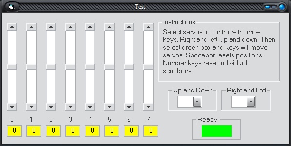
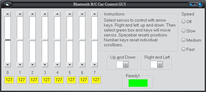
The Visual Basic 2005 version was started after I finished the VB6 version. This later version is absolutely better than the VB6 version. The car is controlled with the arrow keys, as is done in most car driving games on computers.
Code is available below the control GUI screenshots.
As I've worked through the coding and testing, my program and (more tangibly) the interface has changed quite a bit. Here a few choice screenshots of the GUI's development.

- Zipped archive with entire VB.NET 2005 project within.
- Functional code (.txt)
- Layout code (.txt)
|
 |
 |
 |
 |
 |
 |
 |
 |
|
 |
 |
 |
 |
 |
|
 |
 |
 |
 |
11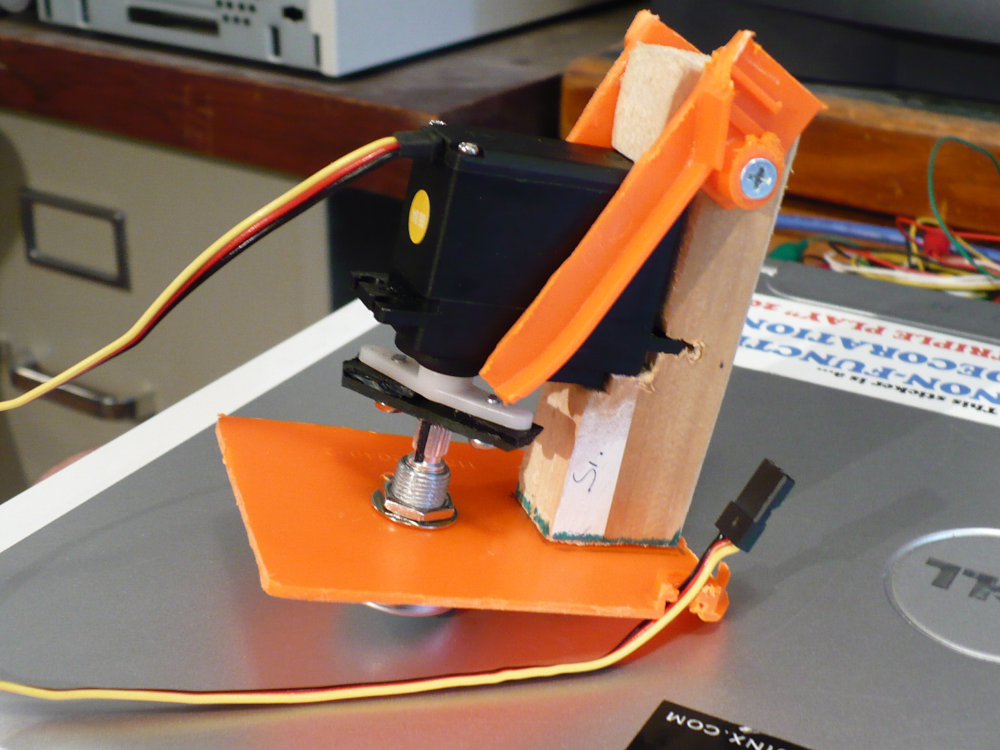 |
 |
 |
 |
 |
 |
 |
 |
 |
 |
 |
 |
 |
 |
- The guide
- Society
of Robots, especially:
- Bluetooth robots
- Servos
- Forum thread where I trouble-shot bluetooth connection problems
- The MiniSCC II Homepage with a plethora of information
- Some dude's page about the NIKKO Alienator
- Jameco's Robot Store... huge selection. Got some stuff here and other stuff cheaper elsewhere.
- eBay.com.... where you can get most things cheapest